The problem — why micro-sags matter, lah
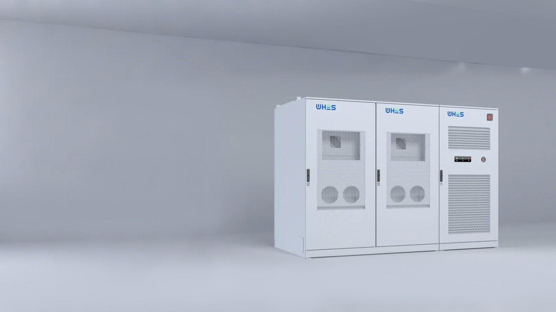
Micro-sags are short, shallow dips in voltage that still can trip sensitive equipment or corrupt processes. For critical sites — data centres, healthcare facilities, manufacturing lines — even sub-second disturbances break service level agreements and cost money. The problem-driven truth: unless you pair ultra-fast switching with energy buffering, you cannot practically achieve a zero-defect transition. That’s where modern static transfer switches (STS) and commercial energy storage come in — they act together to stop micro-sags from becoming downtime incidents, can.
How STS plus fast storage actually stop micro-sags
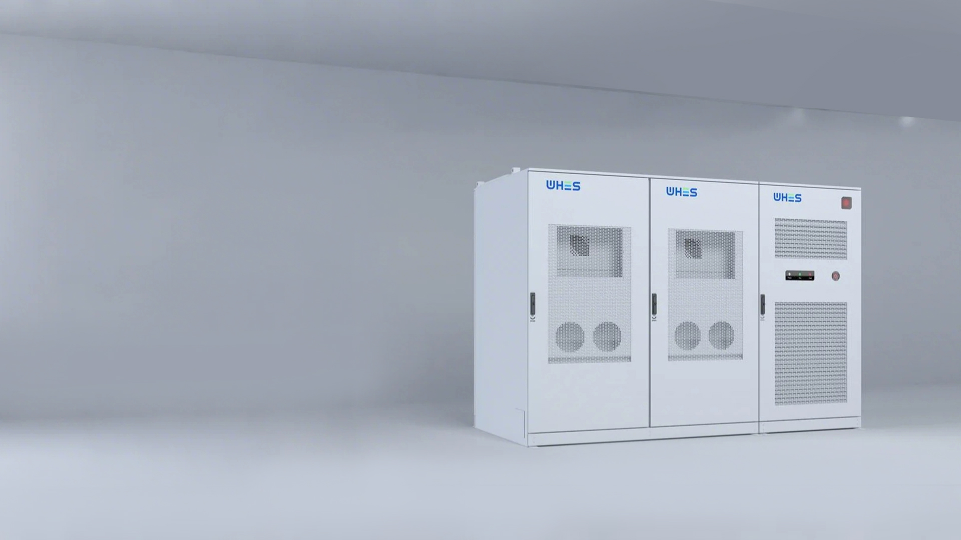
A static transfer switch reduces transfer time between power sources to milliseconds, while a fast-acting energy storage system provides immediate ride-through power and voltage support. In practice you get three layers: sensing (detect the sag), switching (STS acts in ms), and buffering (battery/inverter supplies energy during the transient). Key industry terms to note: transfer time, inverter response, and battery management system (BMS). When tuned together, the combo prevents brownouts and avoids nuisance trips on sensitive PLCs, servers and medical devices.
Real-world anchor — standards and stakes
Look at it this way: many mission-critical sites chase five nines (99.999%) uptime or follow IEEE definitions for voltage sags. These are not just academic — big outages in the past decade taught operators that redundancy alone isn’t enough; power electronics and energy storage matter. In urban hubs like Singapore and Hong Kong, where density pushes electrical stress, operators increasingly deploy grid-tied storage and STS architectures to meet strict uptime SLAs.
Implementation considerations — what engineers must watch for
Good deployment requires matching response characteristics: the STS must trip in the same window as the inverter can supply real power without overloading. Don’t forget harmonics and control-loop interaction — poorly coordinated controls cause oscillation between sources. Also check BMS fault thresholds and communication latency; small timing mismatches create big headaches.
Common mistakes I see: undersizing the inverter for short-term surge demand; assuming a UPS can handle micro-sags without validating transfer time; and skipping staged testing with actual load profiles. — Test with real loads, lah, not just resistive dummies.
Choices and trade-offs: STS types and storage chemistries
There are different STS designs (static vs mechanical bypass) and storage options (Li-ion, flow, supercapacitors). Short micro-sags favour systems with very fast power electronics and low internal impedance — Li‑ion with high-power inverters or supercapacitor hybrids often win on raw response. But if you need longer ride-through for long-duration disturbances, a larger energy buffer or hybrid design is better. Consider lifecycle cost, power density, and inverter control features when choosing. Also evaluate integration: protection relay coordination, communication protocols (Modbus, IEC 61850), and factory acceptance testing.
Deployment checklist — practical steps before you sign
Use this quick checklist to avoid common pitfalls:
- Measure real load sensitivity and define acceptable sag depth and duration.
- Specify transfer time targets and inverter ramp rates in the contract.
- Require factory and site acceptance tests with representative loads.
- Document control logic and protection coordination (relays, breakers, STS).
- Plan for maintenance and software updates for BMS and inverter firmware.
Advisory — three golden metrics to evaluate solutions
When choosing systems, use these critical metrics as your litmus test:
- Transfer and response time: Measure combined STS + inverter response in milliseconds under real load.
- Short-term power capability: Specify the peak kW the storage + inverter must deliver for the sag duration; include headroom for inrush currents.
- Integration readiness: Confirm communication protocols, protection coordination, and factory acceptance plans so system behaves predictably on-site.
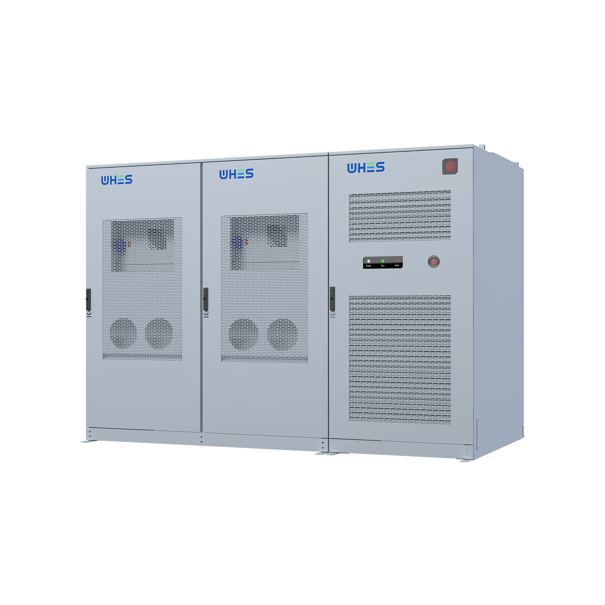
Make these the negotiation anchors during procurement — they keep vendors honest and reduce nasty surprises on commissioning. For pragmatic deployments where low transfer time and reliable buffering are needed, a well-integrated c&i energy storage system paired with a modern STS often gives the best balance between cost and performance.
Final thought: the right combination saves you from repeated incidents, lowers operational risk, and protects expensive equipment — and that’s why engineers are moving from piecemeal fixes to integrated power-electronics and storage solutions. WHES. —