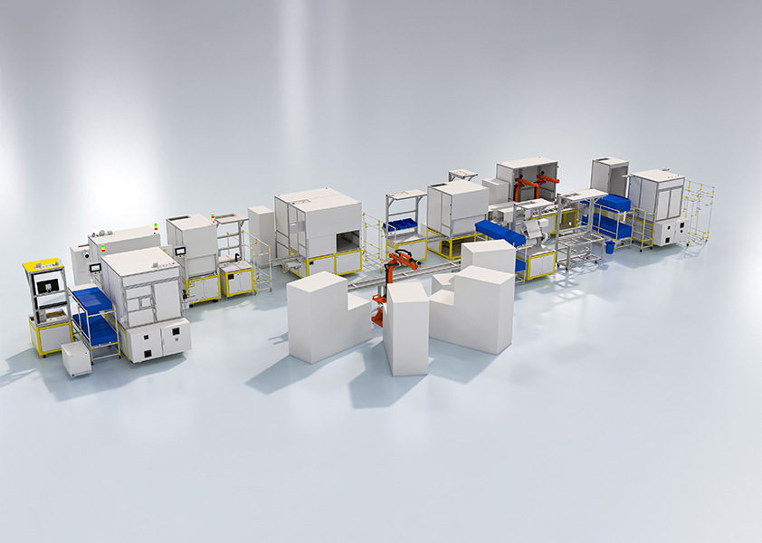
Diagnosis: where factories lose time and money
Most problems begin with a simple fact: the plant was designed for yesterday’s volumes and today’s product mix. That mismatch shows up as frequent line stoppages, uneven takt times and hidden work that operators shoulder without guidance. Experience from audits — including observations at Toyota’s production lines in Japan — shows these failures are rarely about a single robot or PLC; they are about layout logic, capacity buffers and poorly defined process handoffs. Early consideration of automotive automation helps avoid wasting space and investment on systems that cannot be balanced to real takt times.
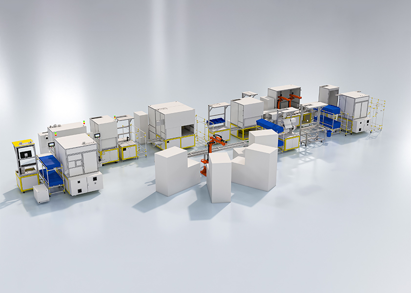
Primary layout problems to fix first
Address these layout issues before equipment selection. The order in which you solve them determines whether automation will pay back.
– Workflows that cross each other, creating congestion and quality risk.
– Poor access for maintenance, so simple failures create long downtimes.
– Fixed line modules that prevent right-sizing capacity for variants.
– Storage placed too far from point of use, increasing handling time.
Capacity planning mistakes that escalate cost
Capacity is more than peak throughput. Many engineers overspec systems for rare peaks and starve the line the rest of the time. The correct approach measures realistic demand profiles, includes short-term growth plans, and defines minimum sustainable takt time. Use 80/20 demand analysis to size buffers. Staff flexibility will absorb variance far cheaper than oversizing conveyor runs or buying extra robots that remain idle.
Process requirement gaps that matter most
Clear, measurable process requirements let you match control systems to physical design. Define these before you buy: cycle time per station, allowable positional tolerance, required inspection frequency, and fault-recovery procedures. If a process needs sub-30-second tooling changes, design the workbench and the tooling changeover together rather than retrofitting later.

Practical design steps: from problem to solution
Follow this problem-driven sequence to prevent rework and scope creep.
1. Map current state visually, capturing takt time, changeover steps and idle time.
2. Identify the single biggest constraint; solve it with layout or operator support, not automation first.
3. Simulate proposed cell layouts with discrete-event models to confirm throughput and staffing needs.
4. Pilot one module at line speed before scaling; validate recovery and maintenance procedures.
5. Roll out with defined acceptance tests tied to quality and availability metrics.
Technology choices: pick tools that address specific faults
Select technology only to fix identified problems. Collaborative robots suit tasks needing quick redeployment; fixed-arm robots suit high-repeatability welds or paint. Vision systems solve misalignment and presence checks; conveyors solve predictable transport, not process variance. Plan for real-world issues: tool change frequency, dust, and operator ergonomics. Consider how a proposed cell would integrate into an automated automotive assembly line and whether its diagnostics feed into plant-level OEE monitoring.
Common pitfalls and how to avoid them
These mistakes recur on site and they are avoidable.
– Treating automation as a solution to poor work design. Fix process first.
– Ignoring maintenance access for speed of installation; you’ll regret it at first breakdown.
– Underestimating spare-parts needs for custom end effectors.
– Failing to define acceptance tests that mirror real production, leading to false confidence.
Quick checklist for final design sign-off
Before commit, confirm these items:
– Documented takt and validated simulation results.
– Recovery and lockout procedures tested at line speed.
– Ergonomic review completed for all manual tasks.
– Spare-parts and trained maintenance coverage defined.
– Data streams mapped from cell controllers to plant historian and QA systems.
Conclusion — what this solves and why it works
A problem-driven approach forces teams to confront the true causes of stoppage and variation: layout, capacity mismatch and unclear process requirements. Solve those first, choose technology that responds to the identified faults, and validate with a pilot under production conditions. This method reduces wasted capital and speeds stable uptime; it’s the practical route used by engineering teams I have worked with across East Africa and beyond and mirrors the applied methods at firms such as FHS in aligning plant layout to realistic operational needs.